Copper (Sulfide)
CuFeS₂ / Cu₂S
Primary flotation may use a xanthate collector. Concentrate grade, recovery, and reagent scheme must be established by representative mineral testwork.
Froth Flotation
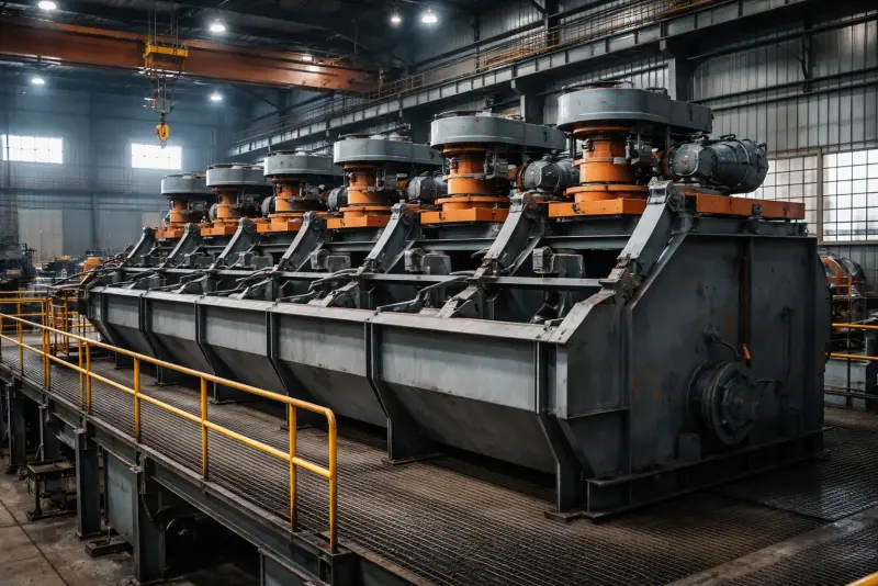
SF flotation cells for copper sulfide, lead-zinc, graphite, fluorite, and gold-bearing sulfide recovery. The self-aspirating SF series covers 7 cell sizes from 0.37 to 20 m³ for rougher, cleaner, and scavenger banks without a separate air blower.
Need SF-8 or SF-16 layout support? After duty confirmation, we provide outline drawing guidance, motor layout references, and cell-bank arrangement suggestions for procurement and civil planning.
Flotation exploits surface chemistry: valuable mineral particles are made hydrophobic by chemical reagents, then selectively attach to air bubbles and float to the surface as a mineralised froth — while gangue minerals stay wetted and sink.
01
Ore is ground to liberation size (typically 75–150 µm) in a ball mill. Reagents (collector, frother, pH modifier) are added and mixed with the slurry in conditioning tanks to coat mineral surfaces.
02
Slurry enters the flotation cell. The self-aspirating impeller draws air down the hollow shaft, while the stator disperses it through the pulp. Bubble-size distribution must be confirmed under the proposed air rate, reagent programme, and slurry conditions.
03
Hydrophobic (collector-coated) mineral particles collide with air bubbles and attach. The bubble-particle aggregates rise buoyantly to the surface, forming a stable mineralised froth layer.
04
Mechanical scrapers continuously push the mineralised froth over the overflow weir into the concentrate launder. Gangue slurry exits from the cell bottom as tailings.
A complete flotation plant uses multiple stages in series, each with a bank of SF cells. Grade and recovery are balanced across the circuit.
Rougher
First-pass flotation targets a rougher concentrate while rougher tails continue to the scavenger stage. Grade lift, reagent dosage, and residence time are ore-specific and must be established by testwork.
Scavenger
Processes rougher tailings to capture remaining mineral value. Low reagent dosage, coarse froth setting. Scavenger concentrate (low grade) is recycled back to the rougher or cleaner feed.
Cleaner
Upgrades rougher concentrate to final saleable grade. Less residence time needed, fine froth, low collector. Multiple cleaner stages (2–3 stages) progressively raise grade. Cleaner tails return to rougher.
Re-Cleaner
An optional additional cleaning stage may be evaluated for higher-grade targets. Each added stage changes the grade-recovery balance and must be justified by locked-cycle testwork.
Typical minimum circuit: Rougher + Cleaner + Scavenger
A rougher, cleaner, and scavenger arrangement is a common starting point, not a recovery prediction. Required stage count, concentrate grade, recovery, and any combined process must be confirmed by representative locked-cycle testwork.
7 cell sizes from 0.37 m³ (lab / pilot) to 20 m³ (large-scale production). All models are self-aspirating — no external air blower required.
| Model | Cell Volume | Capacity | Impeller Dia. | Motor Power | Weight | Get Quote |
|---|---|---|---|---|---|---|
| SF-0.37 | 0.37 m³ | 0.2–0.4 m³/min | 300 mm | 1.5 kW | 0.45 t | Quote |
| SF-1.2 | 1.2 m³ | 0.6–1.6 m³/min | 450 mm | 5.5 kW | 1.8 t | Quote |
| SF-2.8 | 2.8 m³ | 1.5–3.5 m³/min | 550 mm | 11 kW | 3.2 t | Quote |
| SF-4 | 4 m³ | 2–4 m³/min | 650 mm | 15 kW | 4.1 t | Quote |
| SF-8 | 8 m³ | 4–8 m³/min | 760 mm | 30 kW | 7.5 t | Quote |
| SF-16 | 16 m³ | 5–16 m³/min | 850 mm | 45 kW | 12 t | Quote |
| SF-20 | 20 m³ | 10–12 m³/min | 850 mm | 45 kW | 14 t | Quote |
* Capacity in m³/min refers to pulp flow rate through the cell bank, not ore tonnage. Tonnage depends on ore specific gravity and solids concentration. Convert the t/h requirement to cell volume only after those inputs and the testwork residence time are documented.
SF cells can be evaluated for copper sulfide, lead-zinc, graphite, fluorite, and similar flotation duties after mineralogy, liberation, reagent response, residence time, and air demand are established.
CuFeS₂ / Cu₂S
Primary flotation may use a xanthate collector. Concentrate grade, recovery, and reagent scheme must be established by representative mineral testwork.
PbS / ZnS
Sequential differential flotation — float lead first with low pH, then activate zinc with CuSO₄. SF machines handle both stages.
Au in pyrite / arsenopyrite
Float the sulfide carrier mineral with xanthate; gold follows. Concentrate then goes to CIL or smelting.
MoS₂
Bulk Cu-Mo flotation followed by selective depression is one possible route. Final Mo grade and recovery require representative testwork and assay confirmation.
CaF₂
Non-sulfide flotation with fatty acid collector. Acid-grade CaF₂ is a possible process target, but concentrate grade and recovery require mineral testwork and assay confirmation.
C (crystalline)
Natural graphite is naturally hydrophobic — light collector dosage only. SF machines produce flake graphite concentrates.
—
De-ashing of fine coal (<0.5 mm) where gravity separation is ineffective. Diesel oil as collector, MIBC as frother.
NiS / CoAsS
Pentlandite and cobaltite float with xanthate. Circuits typically include magnetic separation to remove pyrrhotite.
These six components interact with slurry properties, reagent conditions, and operating level. Review them together when diagnosing air dispersion, froth transport, grade, or recovery.
Forward-inclined rectangular trough that minimises dead corners and accelerates froth movement toward the overflow weir. Tank geometry directly affects residence time and froth recovery.
Double-sided backward-rake impeller blades create dual circulation: upper zone aerates the pulp; lower zone resuspends settled coarse particles. Low rotation speed (200–400 RPM) reduces reagent shear and wear.
Stationary cage surrounding the impeller that disperses incoming air through the pulp. The resulting bubble-size distribution depends on air rate, pulp chemistry, frother programme, impeller-stator condition, and slurry properties, so it must be measured during testwork and commissioning rather than assumed from a fixed range.
In self-aspirating SF design, impeller rotation creates vacuum that pulls ambient air down the hollow shaft without a blower. Air flow rate is controlled by the intake valve — a critical operating variable.
Overflow weir height sets the froth depth. Mechanical scrapers (paddles) push froth over the weir into the concentrate launder continuously. Scraper speed affects froth retention time and concentrate grade.
Controls pulp level inside the cell to maintain consistent froth depth. In a multi-cell bank, the level in each cell is set independently to optimise recovery progression from rougher to scavenger.
Flotation circuit design requires mineralogy, grind size, target concentrate quality, slurry flow, and representative metallurgical testwork before cell volume or stage count is fixed.
Step 01
Calculate total cell volume from measured slurry flow and the residence time established by representative testwork. Divide the resulting bank volume by the selected cell size, then confirm short-circuiting allowance and operating level in the written design basis.
Step 02
Larger cells (SF-8, SF-16, SF-20) reduce capital cost and floor space per m³ of volume. Smaller cells (SF-0.37, SF-1.2) offer finer control in lab and pilot circuits, or when handling low-volume high-value streams.
Step 03
A rougher, cleaner, and scavenger arrangement is one starting point. Low-grade, fine-grained, or complex ores may need a different stage count; confirm the number of cells and recycle streams from locked-cycle testwork.
Step 04
Confirm chemical compatibility for every reagent in the proposed circuit. If cyanide is present, require written compatibility for shaft seals, rubber linings, and all wetted materials before ordering.
Need a flotation circuit review?
Tell us: ore type, feed grade (%), target concentrate grade, daily throughput (t/d), and grind size target. We can prepare a first-pass rougher–cleaner–scavenger basis for review against your testwork, including candidate cell count, cell size, and reagent questions.
Flotation cells are mechanically simple. Most performance issues are process-related (reagent dosage, pH, grind size) rather than mechanical — operators should learn to read the froth.
Operating checks
Planned inspection
Condition-based service
FAQ
Short answers to common procurement questions before requesting quotation.
Need deeper context?
Flotation is the recovery stage, but recovery starts with the grind. Treat the equipment below as a process sequence; capacity matching and liberation targets require a documented circuit design.
Project brief
Share four operating inputs so we can rule out unsuitable models early and explain the assumptions behind the shortlist.