Magnetite Pre-concentration
Magnetite, titano-magnetite
A possible magnetic pre-concentration stage. Feed assay, liberation size, concentrate target, and recovery must be established by representative testwork.
Magnetic Separation
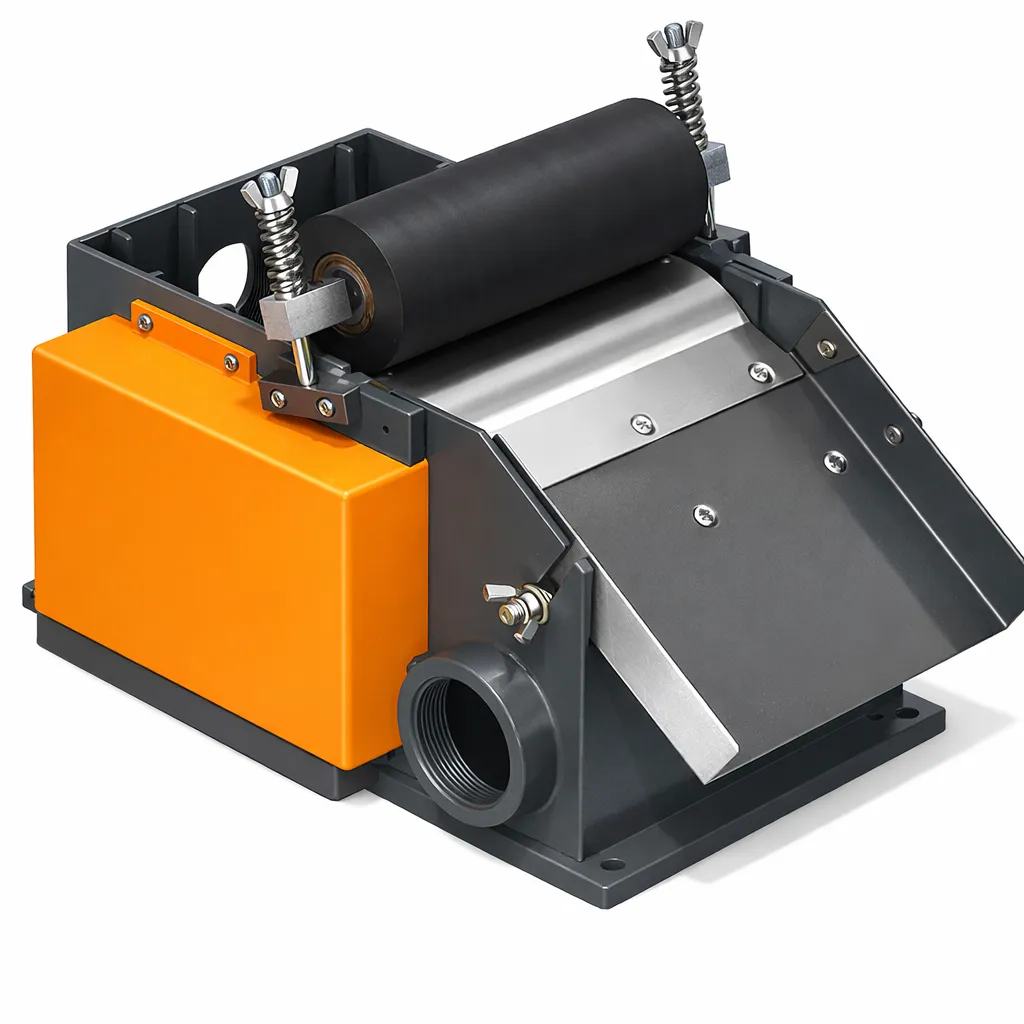
Permanent magnet wet drum separator for magnetite concentration and iron ore beneficiation. No power consumption for magnets, three tank types, and 5 drum sizes from 15 to 140 t/h.
Pricing
We quote per project rather than publishing a single figure, because the same machine name covers models an order of magnitude apart in price. Send your duty and you get a real number back, not a brochure.
Drum size and number of drums
Drum diameter and length set the capacity, and many circuits need roughing and cleaning stages rather than a single unit.
Field strength and magnet type
Gauss rating and whether the magnets are ferrite or rare-earth is the largest single variable in a separator quote.
Drum surface and tank material
The drum covering and tank lining are specified against your slurry, and abrasive feed shortens the replacement interval.
Drive and frame scope
Motor rating, reducer, support frame and launders are quoted separately from the separator itself.
Send the material, your required t/h and the destination port. That is enough for a quote — you do not need a full specification first.
Get Price on WhatsAppTypical reply within 12 hours · English and Chinese
A fixed permanent magnet assembly inside a rotating non-magnetic drum attracts magnetic particles to the drum surface. As the drum rotates, magnetic particles are carried out of the slurry while non-magnetic particles drain away.
01
Pre-ground ore slurry (20–40% solids) is fed evenly across the full drum width through a distribution box. Feed rate and % solids are the two most critical process variables.
02
The inner magnet assembly generates a radial field of ≥120 mT at the drum surface. Magnetite particles (SG 5.2, strongly magnetic) are pulled from the slurry and adhere to the rotating drum shell.
03
In CTB counter-rotation, the feed moves toward the drum while the drum surface moves away. This relative motion promotes drainage and washing of non-magnetic gangue particles off the concentrate layer.
04
As the drum rotates past the magnet's coverage arc, the field weakens and magnetic concentrate falls by gravity into the concentrate launder. Tailings exit through the overflow end.
| Property | Wet (CTB) | Dry (Belt/Drum) |
|---|---|---|
| Mineral Type | Strongly magnetic (magnetite, ferrosilicon) | Strongly magnetic, medium magnetic |
| Feed Moisture | Slurry (20–40% solids) | Dry (<1% moisture) |
| Particle Size | < 3 mm | 0.1–20 mm |
| Field Strength | Confirm ordered model certificate (published models list ≥120 or ≥135 mT) | Up to 400 mT (strong magnetic) |
| Separation Efficiency | Ore-specific; confirm by testwork | Mineral-specific; confirm by testwork |
| Typical Application | Iron ore beneficiation, DM recovery | Iron removal from industrial minerals, conveyor tramp iron removal |
5 drum sizes. All models: permanent magnet, counter-rotation CTB tank, field strength ≥120 mT at drum surface, max feed size 3 mm.
| Model | Drum Size | Field Strength | Drum Speed | Capacity | Motor Power | Weight | Get Quote |
|---|---|---|---|---|---|---|---|
| CTB-618 | Φ600×1800 mm | ≥120 mT | 40 r/min | 15–30 t/h | 2.2 kW | 1.5 t | Quote |
| CTB-712 | Φ750×1200 mm | ≥120 mT | 35 r/min | 15–30 t/h | 2.2 kW | 2.1 t | Quote |
| CTB-924 | Φ900×2400 mm | ≥135 mT | 25 r/min | 30–55 t/h | 4 kW | 3.8 t | Quote |
| CTB-1030 | Φ1050×3000 mm | ≥135 mT | 22 r/min | 80–120 t/h | 7.5 kW | 6.2 t | Quote |
| CTB-1230 | Φ1200×3000 mm | ≥135 mT | 17 r/min | 100–140 t/h | 7.5 kW | 9.5 t | Quote |
* Capacity for magnetite ore slurry at 30% solids. Capacity varies with ore magnetic susceptibility and feed % solids.
CTB separators can be evaluated for magnetite beneficiation, dense-medium recovery, de-ironing, and selected waste-recovery duties after feed and product targets are defined.
Magnetite, titano-magnetite
A possible magnetic pre-concentration stage. Feed assay, liberation size, concentrate target, and recovery must be established by representative testwork.
Magnetite in tailings
Re-processing of historical tailings ponds to recover residual magnetite that was not captured in original circuits.
Iron-bearing steelmaking slag
Recovers metallic iron particles from granulated slag for recycling back to the furnace. Reduces waste disposal costs.
Ferrosilicon, magnetite DM
May recover ferrosilicon or magnetite from coal-preparation circuits for reuse. The achievable recovery and resulting medium-consumption change require a measured circuit balance.
Iron-stained quartz sand
May remove iron-bearing minerals from glass sand or ceramic raw materials. The required Fe limit and achievable product must be confirmed by assay and testwork.
Copper, zinc ore with magnetite
Magnetic pre-concentration removes magnetite gangue before flotation, reducing reagent consumption and improving selectivity.
Six key components — understanding each helps with troubleshooting concentrate grade and recovery problems.
Multiple magnetic poles are arranged around the drum interior using NdFeB or ferrite magnets. The permanent-magnet assembly requires no excitation power; field retention and service interval must be confirmed from the magnet grade, operating temperature, measurements, and supplier documentation.
Thin non-magnetic stainless steel shell rotates in the field generated by the fixed inner magnet assembly. Drum surface texture is smooth for easy concentrate discharge.
The feed slurry flows through the trough around the lower portion of the drum. Tank type (concurrent, counter-rotation, semi-counter) determines the separation mechanism and product quality.
Low-speed motor and gear reducer drive the drum at 17–40 RPM depending on model. Drum speed affects residence time in the magnetic field and separation selectivity.
Magnetic concentrate clings to the drum surface and exits through a scraperless chute at the top of the arc, beyond the magnet assembly end, where the field weakens and releases the material.
A movable splitter plate between the drum and trough adjusts the partition between concentrate and middling/tailing streams to optimise grade-recovery balance.
Four factors determine the right CTB model and circuit configuration for your magnetite project.
Step 01
CTB series is effective for strongly magnetic minerals: magnetite (Fe₃O₄), pyrrhotite, ferrosilicon, metallic iron. For weakly magnetic minerals like hematite (Fe₂O₃) or siderite, a high-intensity wet magnetic separator (WHIMS) is needed instead.
Step 02
Compare CTB, CTA, and CTN against the required grade-recovery balance, slurry loading, feed size, and tank geometry. No tank arrangement should be selected as the universal throughput, grade, or recovery winner without representative testwork and the ordered model's hydraulic basis.
Step 03
Published model ranges run from CTB618 at 15–30 t/h to CTB1030 or CTB1230 at 80–140 t/h. Do not apply a fixed spare-capacity percentage: set design margin from measured slurry flow, solids loading, feed variability, availability target, wear condition, and the duty of each separation stage.
Step 04
CTB separators typically operate in 2–3 stages: rougher (first pass), cleaner (concentrate upgrade), and scavenger (tailing recovery). Each stage may use a different tank type to optimise overall performance.
Need a magnetic separation circuit design?
Tell us your ore type, feed grade (% Fe), target concentrate grade, and throughput. We'll propose a complete rougher-cleaner-scavenger CTB circuit with flow balance.
CTB separators are mechanically simple. Most issues arise from drum surface build-up, bearing water ingress, and feed slurry density variation.
Operating checks
Planned inspection
Condition-based service
FAQ
Short answers to common procurement questions before requesting quotation.
Need deeper context?
A CTB circuit can be evaluated for liberated magnetite, but feed grade alone does not determine a saleable product. Establish the grade-recovery curve, impurity limits, moisture target, and circuit arrangement with representative testwork before setting commercial expectations. Where slurry temperature changes materially by season, validate separate hydraulic operating windows; a warm-season trial does not by itself establish winter feed density, water-recycle, or recovery limits.
Feed assay
Baseline Input
Measure Fe grade, mineralogy, magnetic susceptibility, and liberation before selecting the circuit.
Target assay
Concentrate Basis
Define the required product grade and penalty-element limits in the written testwork brief.
Testwork
Iron Recovery
No fixed recovery should be assumed; confirm the grade-recovery curve on representative feed.
< 3 mm
Liberation Feed
Grind to liberation first; the CTB separates the slurry below 3 mm.
Submit ore type, mineralogy, feed assay, size distribution, and testwork results so the circuit basis can be documented. Hematite and other weakly magnetic feeds require a separate process review; do not assume CTB performance applies to them.
Document Circuit InputsMagnetic separation is one stage in a larger process. Treat the equipment below as a sequence; liberation, capacity matching, and separation targets require a documented circuit design.
Project brief
Share four operating inputs so we can rule out unsuitable models early and explain the assumptions behind the shortlist.